I admit it: I'm a total geek. I love electronics, programming, 3D printing, 3D art, and vintage Apple hardware. I'm always juggling half a dozen projects. I also enjoy documenting it all: my successes, my failures, my experiences... and everything geeky along the way.
Mini Audi Amp - Version 2 Build | Kevin Rye.net - Main
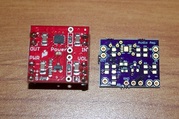
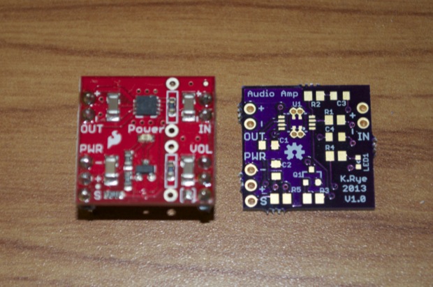
I last left off with my Audio Amplifier PCB being a total bust. Well, not a total bust. It probably works, but I’ll never know. I had ordered the wrong package for the TPA2005D1 chip. As it turned out, I’d never be able to solder the super-tiny 8SON package that SparkFun had it in their Mono Amp Breakout Board design. It didn’t occur to me to look for the chip in a larger package. Once I received the 8MSOP chips from DigiKey, it was obvious that it was the size to use. It’s a little bigger and looks like I’d have less difficulty soldering it by hand.
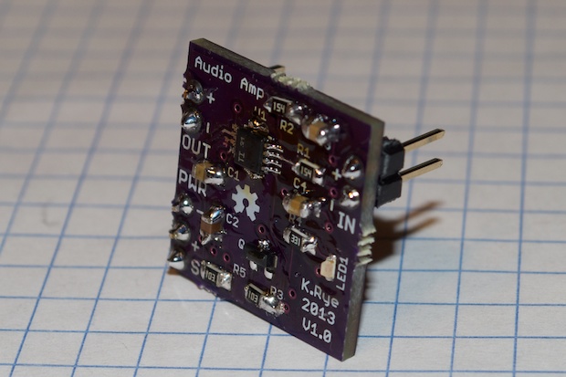
I decided to respin the board and have another one made using the 8MSOP package. I also decided to make V2 breadboard-friendly like SparkFun did with theirs. That way it’ll be much easier to prototype with. It’s just too bad I left “V1.0” on the PCB. I should have changed it to “V2.0”, but at the time I was pretending that the “other” V1.0 didn’t happen.
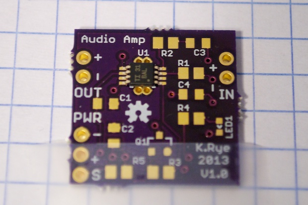
OK, let’s see about soldering this chip. This is going to be tricky.
I made a mess out of it with the flux, but it was necessary. With enough flux, I basically just had to tap the pins to get the solder to flow. I wasn’t as tricky as I thought. It’s all about getting the pins straight on the pads and having enough flux.
It looks pretty ugly, but close inspection with a magnifying glass shows all the pins to be soldered nicely without any shorts.
I do have to admit, I did rush the assembly. I was in the middle of feeding 3 kids, as well as coordinating shower and pajama time. So I knocked it out in 20 minutes. I didn’t even bother filing off the rough bits around the edges that I usually do.
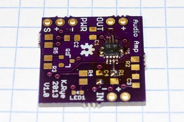
I was basically testing the solder-ability (is that a word?) of the chip. More specifically, my ability to solder the chip. If I pull it off, I can move forward with my LCD V2 Clock project by incorporating the audio amplifier into the design. I wasn’t exactly going for aesthetics here. I just wanted to put it together and validate the design.
I threw it onto my breadboard, connected my speaker and my Arduino, and powered it up.
Sweet. It works! I’ve come a long way since the FartBox!
There’s a little distortion in the audio but it sounds better in person. The distortion is partly due to the fact that it’s so loud. My clock is going to have a pretty loud alarm!
I’ll put the other 2 audio amps together another day. I’ll take my time with those so they come out a little nicer.